
Part 2 of frame 2. With the ability to churn out tubes on my fiberwinder cheaply and with mildly reckless abandon (see Part 1), I still needed to turn these tubes into a bike. And to do that, I was determined to once again use Calfee Design for my inspiration and use 3D print carbon fiber lug moulds. Calfee got me into framebuilding in the first place, and was where I went to for my bamboo ideas back when I was in high school trying to finish frame 1. Or frame 0, I guess, because that bike didn’t even make it through a single ride. So the record, frame 0 is the one that failed, frame 1 is a champ, has lasted for a few thousand miles and many rough gravel rides. And frame 2 is coming to take its place.
In the posts before about my first frame, I think I may have talked about how I was experimenting with lug mould creation. If not, before I left DC, I was in the process of experimenting with lugs. This was in addition, mind you, to planning and prepping for the Central Asia madness. I left with a pretty solid prototype of a technique that I hoped to implement when I started the next frame. I took the most complex tube intersection, the bottom bracket, and tried to mould the lug. Previously, I had been manually wrapping each lug 6-7 times with cut fabric, and that was just a time-consuming mess.

In the end, my advice to others out there on the choice between the two procedures is this: It was worth every extra hour of the many I spent working in CAD programs and printing the moulds, to do it this way. It made great use of the 3d printer, and I’m elated with the look.
The things I decided not to fiberwind were the chain and seatstays. I really like the look of single-piece chainstays and seatstays. But the first time I did this, I didn’t have a sense of how strong carbon fiber was, so I made them big and bulky. So when I designed this one, I was really trying to be conscious of making these parts much sleeker and smaller. Moreover, I wanted tighter clearances when I attached them to the dropouts. My CAD skills had also improved quite substantially from the last frame, so I was able to make better moulds for these parts.
I will not be doing this again. It is a mess, and although the pictures look ok in retrospect, I was unhappy with how much trial and error went in to making these strong enough to withstand any force. They were inconsistent, and the moulds eventually broke. On the next frame, I will try to wind each stay independently and choose to deal with the more complex geometry of the lugs instead.

I ultimately chose after some trial and error to wind the stays by hand for the 90-degree plies and top-bottom fabric layers for the others. Wrapping these geometries by hand is tough without getting epoxy everywhere. The fabric is never quite as flexible as I would like, and tends to come unwrapped. It’s also time consuming. There were a few depressing failures in this process, and I don’t recommend it. There is still a 3d-printed mandrel still in there as well, and they’re generally pretty heavy compared to the tubes. These broken stays just didn’t have carbon reinforcement in the right places, and I was able to easily break them with my hands. My technique got better though, and the final results have been good. There is room for improvement though.


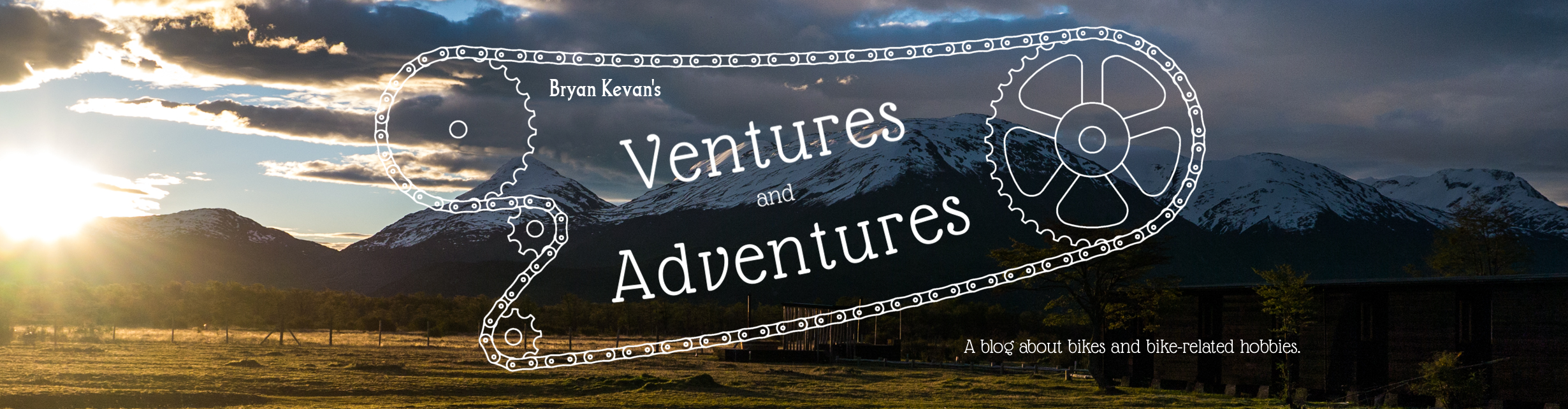
Eventually I got two that worked, and with all the tubes and stays created, I was ready to move on to layup. To lay everything up, I used some extra 20/20 aluminum extrusions I had around to turn my fiberwinder into a fiberwinder/framebuilding jig hybrid. Probably the coolest thing functional thing I’ve ever built, but damn was the alignment process a mess.

I admittedly could have been much more patient in this step. Angry about my performance on my very first statistics midterm in six years, I grew impatient and frustratedly started cutting tubes and throwing them together with little thought. I burned one of my four tubes when I carelessly cut a miter on the bottom of the seattube that was 90 degrees off alignment from the top.
You can see poorly 3d-printed cones held together with zipties, and that made the jig inexact. If I had some better 20/20 joint pieces, I could have really solidified things and gotten much better alignment. As I look at it now, the seat tube is really hangin’ up there without much support or exactness. A .5mm deviation in angle at one end of a tube can turn into a 3-4mm or more deviation at the other side.
Because everything had been designed in the cad program, with moulds printed that were relying on no >1mm deviations, the alignment had to be exact. By the time the tubes were mitered and bonded together (with, shoutout to 3M) a bit of literally unbreakable DP460 aerospace adhesive, there was no going back and re-aligning. What I’m trying to say is that I almost fucked up the whole bike on this step. But I was lucky, and the only consequence is that my rear wheel is by necessity slightly dished and off center because the seattube is at a sliiiight angle.
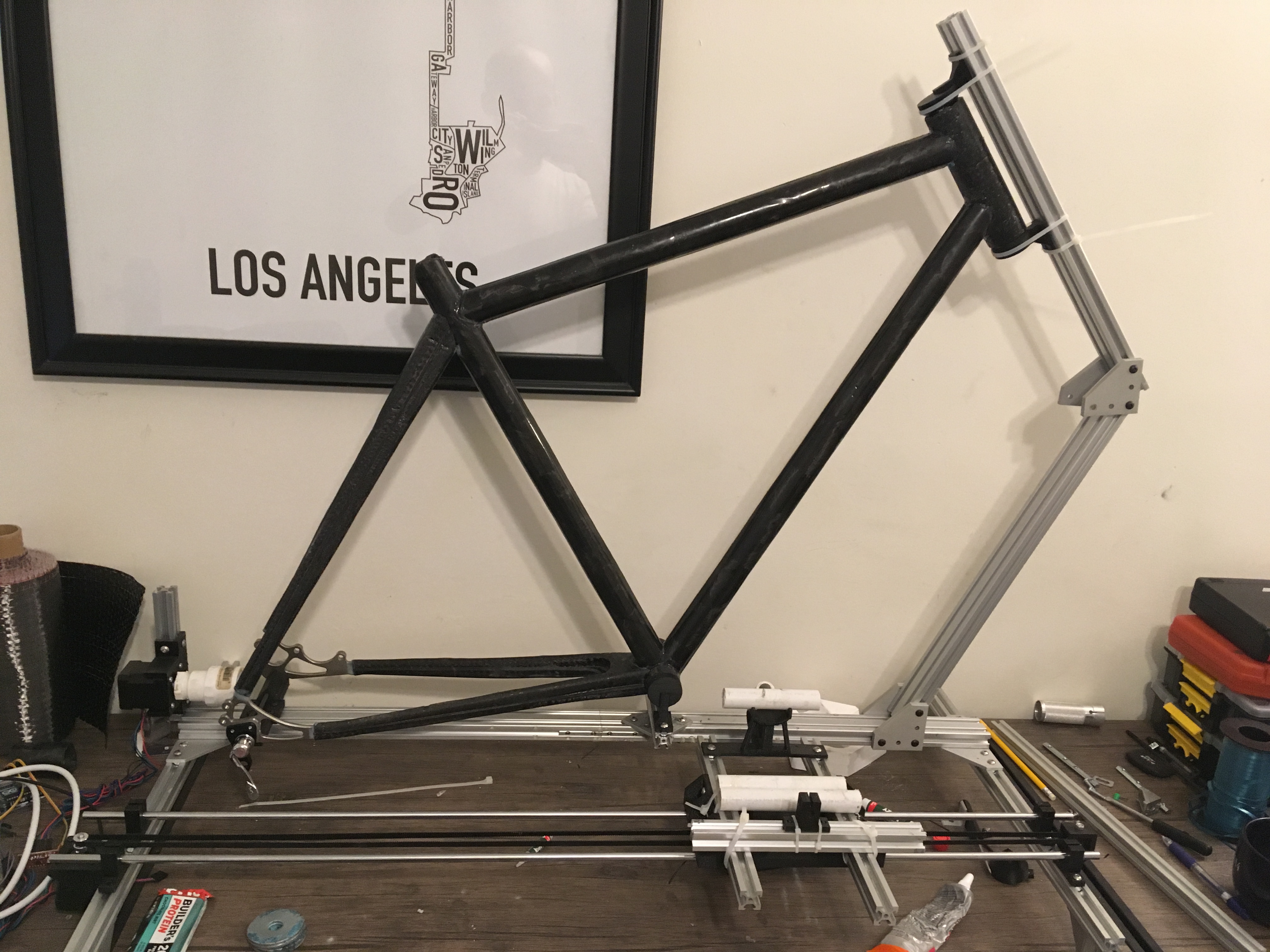
Anyways, the moulds had already been printed, and with the alignment done, I moved on to actually making the lugs. I had purchased a roll of red and black carbon/kevlar weave, and I intended to use it for the exterior layer of the lugs. This fabric turned out to be a bit of a pain to work with. The kevlar is significantly harder to cut with a knife or scissors, doesn’t sand, and although it looks nice from a distance there are some imperfections that could have been avoided.


Clamp time approached. This was it. I was very far into the project, and any screwup now would be devastating. With the first quarter of graduate school bumbling on in the background, I trudged slowly onward.


The moulds ended up working really well. My choice to do the bottom bracket as you see above, with the hole in the center of the mould that could then be cut out, worked perfectly. I was able to replicate my progress from before the trip and implement it in the frame.
The dropouts were attached with that magical 3M product DP460, and then wrapped with 3-4 layers of fiber strand by hand. I can’t say enough about DP460. It’s incredible stuff. Surface prep is important, though, if you want to exert much more pressure on things. A super crazy video can be found of DP420 and I can’t remember off my head which is stronger of if there’s any difference. This stuff is stroooong. It is about $35 for a few oz, but it’s worth it and I have plenty extra.

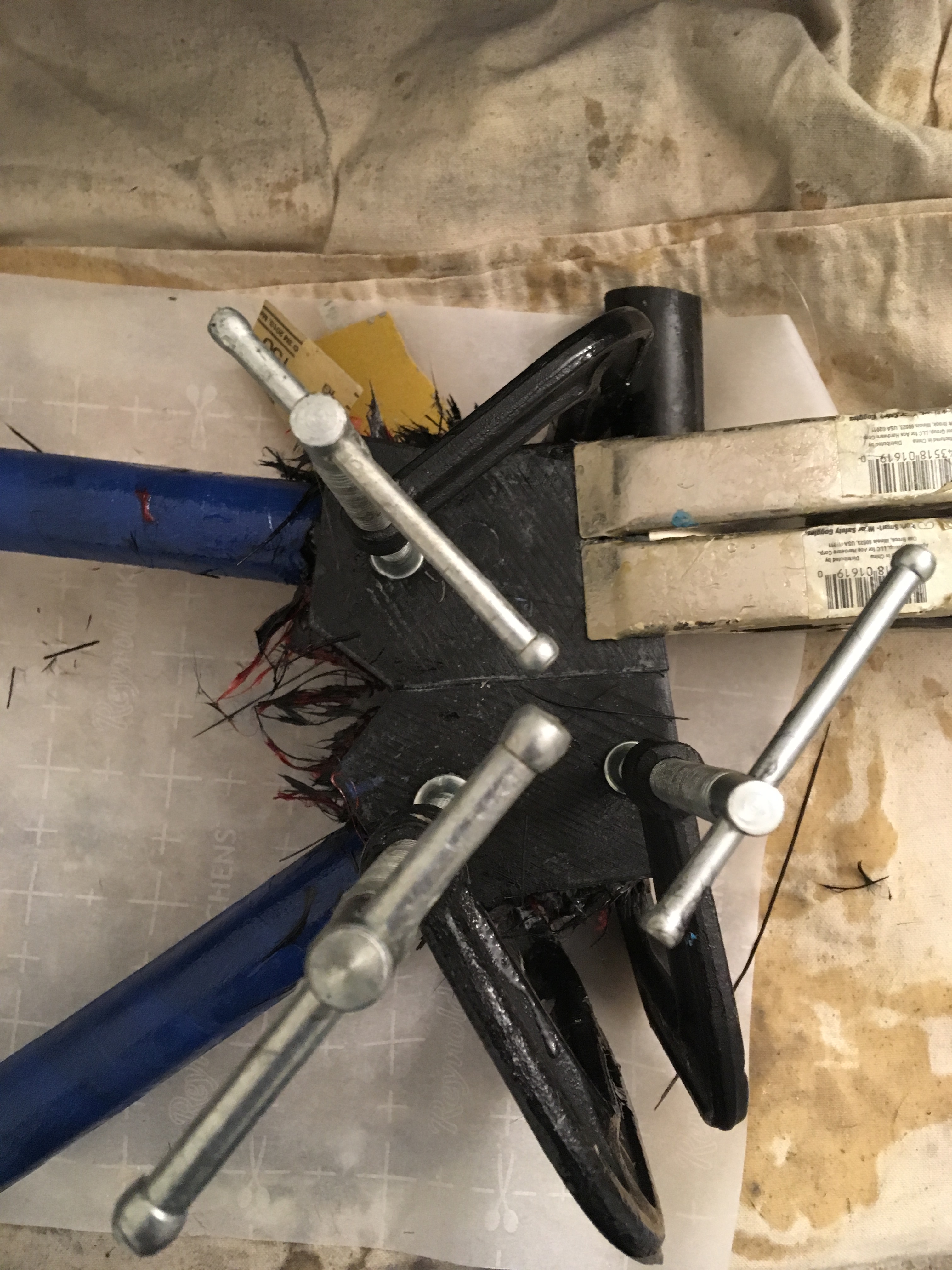
I finished the bike right before the quarter ended, during finals. It runs a SRAM Rival One-by 48t drivetrain, with hydraulic disc brakes, a gravel fork, and 28mm Schwalbe Marathon Plus tires on a gravel fork. There’s about a 71 degree headtube angle and long chainstays, which makes for a very stable but sluggish ride. It is hard-ish to find this geometry on the market, and the mechanics I’ve talked to are always somewhat quick to note this or the large tire clearance. Why a single 48t on a bike that clearly is meant for gravel? Why heavy-as-sin touring tires on a road bike?

Because I wanted it to be literally everything. A gravel bike mixed with a road bike, but also a bike that I’d feel stable and comfortable enough on to ride across a continent. And I suppose that’s pretty on-brand for me. I named the bike Pamir, after the Pamir Mountains. That was a tough few weeks of riding in Tajikistan, and I felt like commemorating that experience on the bike that I designed while riding there. I don’t think I’d take this bike back there, but I would like to take it on an adventure somewhere soon.
I also upgraded the decals on the bike from the first frame as well, stealing yellow/gold designs from the Kazakh flag. The Pamirs aren’t in Kazakhstan, but there are eagles.

The bike now has about 500 miles on it, as I was riding a lot over winter break and in this first bit of January. Shoutout to the UCLA Cycling Team, who were on hand to watch it spread its wings at winter training camp in San Diego two weeks ago. I am becoming more of a roadie by the day.

That’s all. Until next frame. Or trip. Or some other bike thing.

Subscribed. This is the coolest thing. I envy your ingenuity.
LikeLike
Fantastic project… I am trying to build a winder as well using an uno and some nema 17’s. could you share your code you used on you Arduino?
LikeLike